Marine transport of carbon dioxide captured from industrial centres to storage sites is a nascent business whose challenges are being addressed by players such as Norway-based Brevik Engineering.
Building on its naval architecture heritage and experience in about 120 floating production, storage and offloading vessel projects, the company has been closely involved in broader industry studies in northwest Europe to determine the optimum design of CO2 transport vessels.
Working with its Chinese parent company, CIMC Group, Brevik has developed a vessel design that aims to transport CO2 captured from a steel plant in northern France to Norway.

Carrying any form of gas by sea has innate design and engineering challenges and CO2 is no different, according to Martin William Hay, Brevik’s business development manager, who has been involved in CO2 transport studies for five years.
The company’s focus centres on CO2 transport routes between ports on the southern North Sea, although another possibility being eyed is transporting the gas via river barges to storage hubs on the Lower Rhine.
Brevik is also looking at open ocean, or “blue water” transport of large quantities of CO2, but sees that market as “further into the future”, Hay says.
Article continues below the advert
Dry ice problem
To transport CO2 by sea, it must first be chilled and turned from gas into liquid.
However, care must be taken during this process because if CO2 is not pressurised sufficiently during cooling it can become solid “dry ice”.
Ideally, the CO2 would be pressurised to a minimum of 5.8 bar and cooled to minus 56.4 degrees Celsius, Hay says.
However, he explains that when plotted on a graph, this particular pressure-temperature mix intersects very close to what is called a “triple point” where CO2 can exist in all three states and can therefore turn directly from gas to a solid.
“You risk a lot of problems, so what you do [to avoid the dry ice issue] is have higher pressures and also slightly higher temperatures.”
Steel choice
But the challenge with higher pressures and temperatures is that the storage tanks holding the CO2 become bulkier and need either thicker steel walls or must be made of high-tensile steel.
Thicker steel adds to the weight of ships and results in increased construction and fuel costs, while specialist steel is costly.
Tanks made of thicker steel are also more difficult to fabricate, Hay says.
The jury is still out on what steel should be used to build the CO2 tanks, points out Gisle Nysaeter, Brevik’s technical lead on carbon capture and storage.
“It’s definitely a discussion. As a starting point, we’d probably use carbon-manganese steel. But this can be corroded if you don’t have the right specification of CO2,” Nysaeter says.
As a result, he says “there’s a lot of discussions about how clean the [captured] CO2 should be in order to use carbon-manganese instead of stainless steel, for instance.”
This time around, Brevik and CIMC settled on carbon-manganese steel, which limits the size of tanks that can be built, compared to the high-tensile alternative, but is accepted widely in the industry and is not subject to a lengthy qualification process, Nysaeter explains.
Getting the pressure-temperature balance right is crucial because the storage tanks will determine the vessel’s layout.
“Once the tank design is known, this dictates the design of a transport ship,” Hay notes.
The maximum capacity of present-day vessels that transport CO2 for industrial use is about 2000 tonnes, held in tanks designed to handle pressures of 15 bar and temperatures of minus 30 degrees Celsius.
No true industry standard
These specifications, explains Hay, are “as close as you can get to some kind of industry standard” and form the base case for TotalEnergies’ Northern Lights carbon capture and storage project in Norway, where converted bulk carriers will transport the gas.
Brevik has also evaluated converting bulk carriers, but the current industry focus is on newbuilds.
Hay says the company reckons the “sweet spot” for vessel designs would be to transport 500,000 tonnes per annum — larger than the Northern Lights vessels and able to meet the requirements of most North Sea CCS schemes, which have capacities of about 1 million tpa.
One project Brevik is working on is to design a CO2 carrier to take gas from an Arcelor Mittal steel mill in Dunkirk, France, to a storage site at Kollsnes in Norway.
Out of the steel plant’s annual emissions of 10 million tpa, 1.5 million tpa will initially be captured.
Bi-lobe and tri-lobe tanks
Instead of conventional cylindrical tanks laid head-to-toe in a ship’s hull, Brevik will use “bi-lobe” tanks that offer potential advantages in terms of maximised hull space and greater CO2 storage capacity.
The bi-lobe design — a tri-lobe solution is also available — takes the form of two roughly cylindrical structures joined side-by-side.
Brevik’s proposed LCO2 10800 carrier would hold 10,800 cubic metres of CO2 in low pressure bi-lobe tanks and is designed to be similar to a liquid petroleum gas tanker.
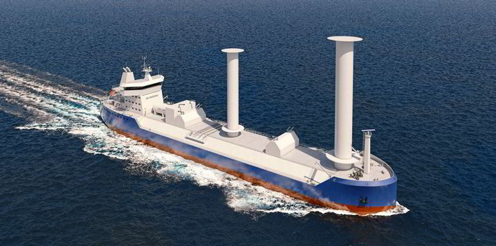
Wind assistance
To minimise fuel consumption and emissions, the vessel could be fitted out with Flettner rotors for wind-assisted propulsion.
Simply put, these rotors are vertical cylinders which spin and develop lift as the wind blows across them.
Nantong-based CIMC Sinopacific Offshore & Engineering has designed the bi-lobe tanks, with Brevik handling the ship design and overall concept.
Hays says the backbone of Brevik’s CO2 strategy is the CO2LOS research and development programme, which also involves TotalEnergies, BP, Equinor, Air Liquide, Imodco, Mitsubishi, Gassco, Sintef, MOL and Sogestran.
Now in its third phase, the CO2LOS project was launched by Brevik and Sintef, the Norwegian research organisation, and receives funding from the government’s Climit programme.